As seen in our surveys and interviews, participants described several pain points. Using our research for the basis of our brainstorm, we explored multiple directions where robots could enhance long-distance relationships:
- Warmth: how can heat send certain signals or messages?
- Pressure: what and how can pressure be used to communicate?
- Eye contact: how might we solve the problem of eye contact during video chat?
- Scent: how might we create a tool to communicate odor?
- Physical contact: how might we simulate physical contact such as cuddling?
We decided to explore pressure and how couples could potentially use it to communicate and increase intimacy.
Process
Initial Sketches
We first drew up sketches of what our robot could potentially look like.
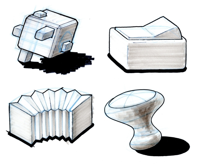
We decided to first build a switch to test user reactions and the technology before potentially building a more complex peg board (drawing inspiration from the below items).


For both robots, the idea is that one partner can press and exert various degrees of pressure, which would be transmitted to the second identical device. The second device would aim to mirror the first. If the second device is pressed upon, then the first device would aim to match it too. Both versions allow couples to communicate in a back-and-forth manner similar to verbal or visual communication but adds the aspect of touch and pressure.
We also desired to create a device that affords the users the greatest degree of flexibility in defining their own physical language to communicate. The toggle switch is such a simple and universally understood mechanism that meaning will come from the creativity of users in defining new modes of communication.
Physical Embodiment
Once we knew our basic form, we began drawing schematics an enclosure to house its internal electronics. We wanted to create a form that feels pleasant to touch, but decided to pursue laser-cut acrylic for our first iteration, since this affords us a faster iteration time. We also wanted this object to be handheld where the toggle is about the same size as the human hand.
By recommendation of Professor Ralph Hollis, a robotics and haptics expert at CMU, we modified an existing device, the Hapkit by Stanford University. The Hapkit is a haptics prototyping platform that uses a dc motor connected to a rocker by a cable to provide haptic feedback to users.

Using the technique employed by the Hapkit we designed our own device such that the toggle is attached to a rocker, which is turned by a dc motor.

Once we knew the precise electronics that we would be using, we then moved on to create more detailed schematics to be converted into laser-cut files.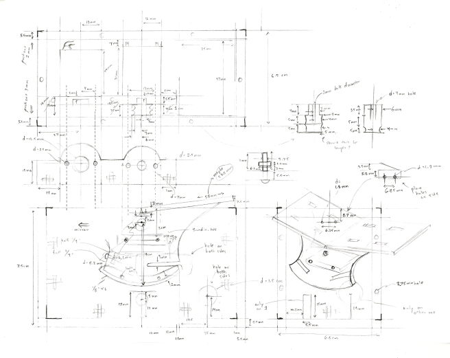
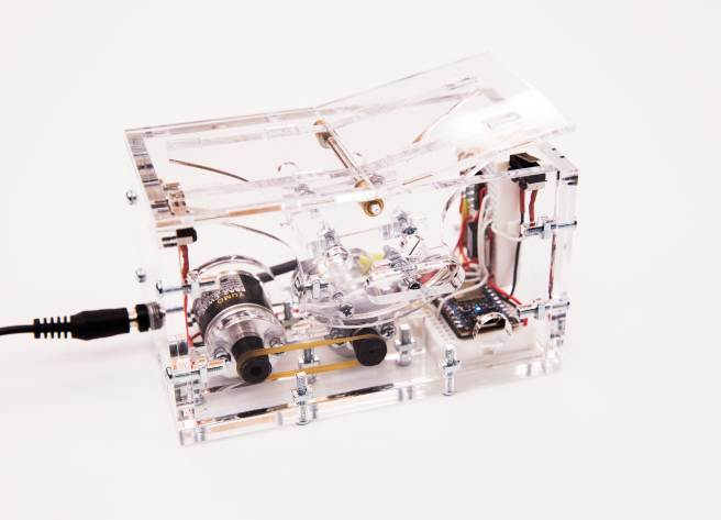
Then, we proceeded to build our first iteration v1.0

And subsequently improved upon this to yield v1.1
Electronics
Arduino seemed an obvious choice for the microcontroller to run the switch, but Arduino is notoriously difficult to work with in IOT applications. Raspberry Pi is great for internet-connected applications, but it’s unable to output PWM for the motor. So, we chose to use Particle Photon instead, which meets both of these criteria.
After some initial testing on the Photon, we discovered that it is incredibly quick at sending information over the internet (there’s a median latency of 25 ms within Pittsburgh). However, the Photon has bandwidth issues, namely: it cannot send publish more than 60 events to the cloud in the last 60 seconds. There’s no limit on the size of each packet sent, but if exceed this volume of packets, we are blocked from sending more until the above criteria (average volume) is met.
This technical limitation poses problems for obtaining a realtime stream of data, so we were forced to use this as a design constraint when designing an algorithm for interaction (described in more detail below, in the Software section).
In addition to the motor, we choose to use a rotary encoder to know the exact position of the switch (in order to, for example, change the amount of pressure applied depending on the position of the switch), and two limit switches to know when the switch hits each side of the toggle. Here’s a wiring diagram of the motor, motor driver, encoder, Photon, and switches:

Algorithm Design
To overcome the bandwidth limitations of the Photon, we choose to pursue a simple switching algorithm in iteration 1. Each toggle will try to achieve the last known position of its “partner” toggle, where position means resting fully on the left or the right side of the toggle. Thus, we have two possible positions {L, R} which only need to be sent over the internet when a limit switch is triggered whose value (L or R) is different than its previous value.
For example, say we have two switches: a green one and a blue one (as below), where each value of t represents a new time.

At the beginning (t=0), both switches are in the same position. The straight arrows indicate the direction the motor will tend to pull in, where dotted lines represent the motor is stationary and solid lines that the motor is actively pulling. At t=1, a finger (in red) begins to push down on the left side of the toggle. At the this moment, the right side of the toggle lifts up off the right limit switch, so the motor begins to pull it on the right side, trying to achieve the same position of the blue toggle. The green motor continues to pull on the right until the moment the finger presses the left side of the toggle all the way down and the left limit switch is triggered, as in t=2. At this moment, a packet is sent from the green toggle to the blue toggle, telling it that its partner switch (green) is in a new (different) absolute position. The blue switch immediately flips to the left, trying to achieve the same position as the green switch. This motion is produced by the motor pulling down on the left side of the toggle, and is represented by the curved solid blue arrow. After the blue toggle achieves this position (t=3), the blue motor stops pulling because it is in an absolute position.
We hope to find ways to send a continuous stream of realtime information in future iterations. The goal is to design the toggle in such a way that users communicate not with it, but through it.
